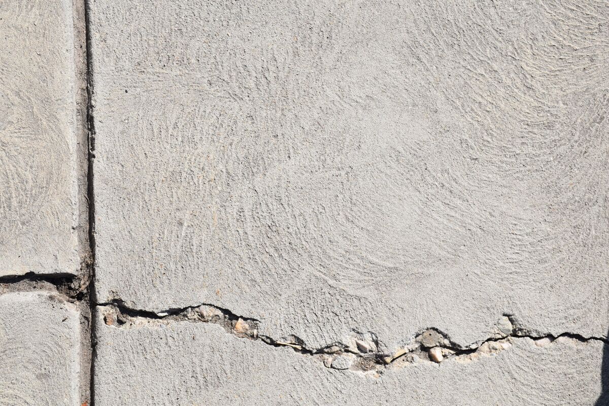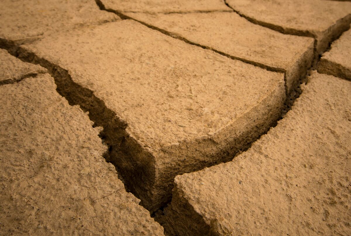
Concrete settlement occurs when the soil supporting a slab compresses, washes out, or shrinks, removing the continuous foundation required to bear weight. While concrete slabs handle extreme downward compressive loads with ease, they possess limited flexural tensile strength. When the earth beneath a sidewalk, loading dock, or parking apron moves downward unevenly, the rigid slab cannot flex to follow the new grade. Unsupported sections bend under traffic and gravity, leading to severe fractures, structural dislocation, and safety hazards.
Managing commercial properties, industrial facilities, and residential associations throughout California requires understanding why these failures happen. Identifying whether a sunken slab indicates a localized void or a broader subgrade failure prevents property managers from spending money on surface fixes that fail within months. When unsupported spans exceed the slab’s load threshold, tensile cracks form along the upper face, signaling that the ground beneath has decoupled from the paved surface.
What Is Concrete Settlement: Uniform Sinking vs. Differential Failure
Concrete settlement is the downward displacement of a slab caused by volume loss, consolidation, or displacement in the underlying subbase. This movement falls into two distinct categories: uniform settlement and differential settlement. The physical consequences of these two mechanisms differ substantially in both structural damage and required remediation.
Uniform settlement occurs when the entire subgrade beneath a slab compresses at a consistent rate. In this scenario, the concrete panel descends as a single rigid plane. Because the slab does not experience twisting or uneven bending moments, structural cracking is uncommon. The practical issues caused by uniform settlement are typically functional rather than structural, such as drainage slopes reversing toward building foundations, threshold transitions becoming misaligned, or utility conduits shearing at structural connections.
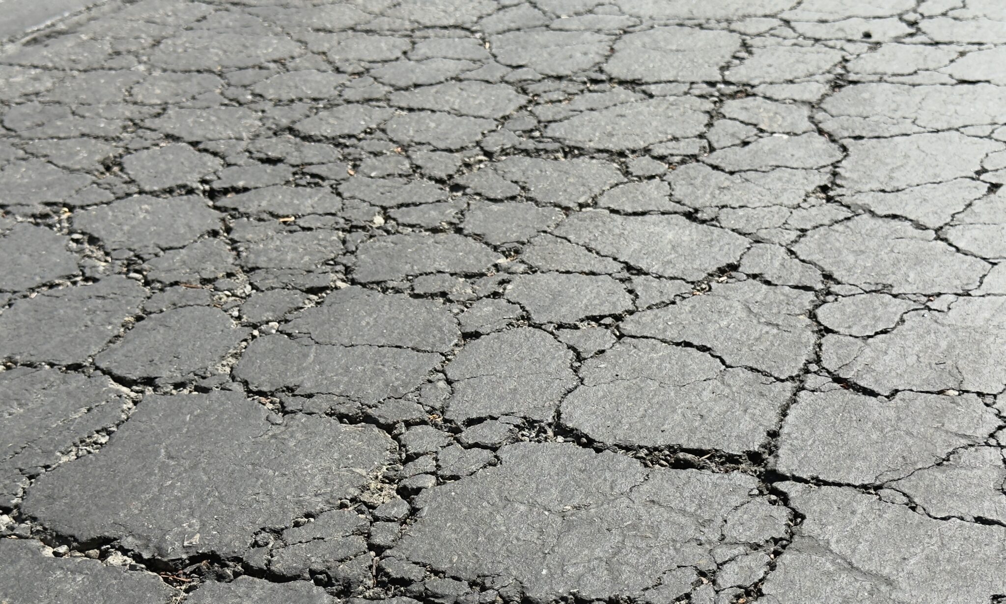
Differential settlement occurs when one portion of the underlying soil subsides while an adjacent section remains stable. This uneven loss of support generates bending stresses inside the concrete panel. Because plain concrete has a tensile strength roughly 10% to 15% of its compressive rating, the unsupported portion of the slab acts as a structural cantilever. Once the stress generated by traffic loads and slab deadweight exceeds the concrete’s tensile limit, fractures appear on the top surface. Differential settlement creates sharp vertical offsets at panel edges, leading to progressive structural destruction and pedestrian hazards.
Primary Geotechnical Causes Behind Soil Subsidence Under Pavement
Soil subsidence under concrete flatwork stems from three primary physical mechanisms: insufficient mechanical compaction during installation, hydro-mechanical soil loss through erosion, and volumetric changes within reactive clay soils.
- Subsurface Erosion and Soil Piping: Water moving uncontrolled beneath a concrete slab strips away fine aggregate particles from the subbase. Broken irrigation lines, misaligned downspouts, and unsealed pavement joints allow stormwater to infiltrate the subgrade. As water flows through the base layer, it carries fine sand and silt particles away in a process known as soil piping. Over several seasons, this wash-out removes cubic feet of structural base material, creating hollow cavities that collapse abruptly when heavy vehicles cross the surface.
- Desiccation and Shrinkage in Expansive Clays: Many regions in California feature high-plasticity clay soils that react dramatically to moisture fluctuations. During extended drought conditions, deep clay layers lose moisture through evaporation and plant transpiration, contracting significantly in volume. This shrinkage pulls the subgrade downward, detaching it from the underside of the concrete slab. When wet weather returns, water re-enters these uneven voids inconsistently, accelerating subgrade instability rather than restoring uniform support.
- Inadequate Subgrade and Base Compaction: When structural fill or native subgrades are placed without meeting geotechnical compaction requirements, gravity and vehicle loads consolidate the loose particles over time. Engineering specifications, such as ASTM D1557 (Modified Proctor Test), typically mandate that structural subbases achieve between 90% and 95% of maximum dry density. When contractors place concrete over earth compacted to lower densities, residual air voids collapse under repeated traffic. The resulting volume reduction leaves open air pockets beneath the slab, directly triggering settlement.

Differential Diagnosis: How to Distinguish Settlement from Heaving
Diagnosing sunken concrete requires determining whether a displacement is genuine settlement or the secondary result of adjacent upward ground movement. Property managers frequently confuse these two distinct failure modes, yet applying a settlement repair to an upward displacement issue can compound the damage.
Concrete settlement pulls the slab surface downward below the surrounding grade. This results in concave slab curvature, water collection over the dropped section, and visible separation gaps beneath the slab edges. When soil settles, adjacent structures like curbs, foundation walls, or adjacent panels stay at their original elevation while the damaged panel drops away. The cracking associated with settlement typically reveals open fissures along the top face as the center of the panel loses support and sags.
Upward movement, on the other hand, is caused by expansive clay hydration or aggressive root growth beneath the slab. In those cases, the center or edge of the slab pushes upward above the adjacent pavement, creating convex crowning, water shedding toward the perimeter, and severe pinch spalling along concrete control joints. If the surrounding soil shows surface uplift, pushed curbs, or mature root lines near the displaced panel, identifying signs of concrete heaving helps rule out true foundation settlement before planning corrective work.
Structural Risks and ADA Compliance: The 1/4-Inch Threshold
Beyond unsightly cracks, unaddressed concrete settlement introduces severe property liabilities, accelerated structural wear, and regulatory violations. In commercial parking lots, public pathways, and retail centers, pavement displacement quickly becomes an urgent management priority.
Under Section 303 of the 2010 ADA Standards for Accessible Design, changes in level on accessible walking surfaces must meet strict geometric tolerances. Any vertical surface offset up to 1/4 inch (6.3 mm) is permissible without edge treatment. Offsets between 1/4 inch and 1/2 inch (6.3 mm to 13 mm) require a mechanical bevel with a slope no steeper than 1:2. Any settled joint or crack that produces an abrupt vertical rise exceeding 1/2 inch without a compliant transition constitutes a trip hazard and an explicit ADA violation, exposing property owners to accessibility claims and premises liability lawsuits.
Settlement also introduces hydraulic and operational deterioration. Sunken slabs collect standing water, which saturates the aggregate base through unsealed joints and accelerates subgrade softening. During winter, standing water creates slip hazards. In industrial applications, such as distribution centers and loading aprons, a 1/2-inch vertical offset damages forklift tires, jars vehicle steering axles, and leads to corner spalling as heavy wheels strike unsupported concrete edges.
Concrete Settlement & ADA Risk Simulator
Select your soil or weather condition, then slide through Years 1 to 10 to inspect void growth, ADA compliance, and repair options.
1.25" Drop — Exceeds the 1/4" (0.25") ADA vertical threshold.
Hollow Air Gap Under Edge
Top Tensile Cracks Forming
Unsupported slab edge creates a trip hazard and risks snapping under vehicle or cart loads.
| Soil / Weather Condition | Years 1–2 (Early Stage) | Years 3–5 (ADA Violation) | Years 6–10 & Engineering Fix |
|---|---|---|---|
| 01. Expansive Clay Soil | 0.15"–0.30" drop; minor shrinkage gap. Seal joints early. | 0.55"–1.25" drop; hollow corner void and tensile cracks. | Up to 2.35" collapse. Lift intact slabs with polyurethane foam; replace fractured panels. |
| 02. Heavy Rain & Runoff | 0.20"–0.45" drop; fine sand washes out at slab perimeter. | 0.80"–1.60" drop; soil piping tunnels erode base support. | Up to 3.25" cave-in. Redirect drainage + inject hydrophobic foam before slab splits. |
| 03. Freeze-Thaw Cycles | 0.10"–0.25" drop; frost heave loosens top base and caulk. | 0.45"–1.00" drop; joint spalling and mid-panel stress cracks. | Up to 2.05" breakup. Lift with closed-cell foam or rebuild with air-entrained concrete. |
| 04. Prolonged Drought | 0.05"–0.15" drop; lawn-edge soil dries and pulls back. | 0.30"–0.65" drop; desiccation pocket forms under edge. | Up to 1.65" tilt. Re-establish uniform bearing with structural foam and joint sealing. |
Repair Decision Matrix: Concrete Leveling vs. Full Slab Replacement
Selecting the appropriate remediation method depends on the structural condition of the concrete panel, the status of the underlying soil, and the planned traffic loading. Property owners often waste capital attempting to lift slabs that are too severely fractured to hold a uniform plane.
| Concrete Settlement Repair Method | Ideal Concrete Slab Condition | Subgrade & Soil Requirements | Curing & Return to Traffic Time | Expected Repair Lifespan |
|---|---|---|---|---|
| Polyurethane Foam Concrete Leveling | Intact panels with drops up to 1.5 inches; minimal secondary cracking | Stable underlying soil with localized subterranean voids | 30 minutes to 2 hours | 8 to 15 Years |
| Traditional Concrete Mudjacking | Medium-to-large unbroken slabs; non-critical aesthetic zones | Stable subgrade capable of supporting heavy slurry weight | 24 to 48 hours | 4 to 8 Years |
| Full Concrete Slab Demolition & Replacement | Severely fractured, spiderwebbed, or sunken panels (> 1.5 inches) | Unstable, saturated, or poorly compacted base requiring rebuild | 3 to 7 days for full cure | 20 to 30+ Years |
Polyurethane foam injection works well for commercial walkways, retail entries, and patios where downtime must be minimal. Technicians drill penny-sized 5/8-inch injection ports through the concrete and inject a two-part expanding polymer. The liquid expands beneath the slab, filling open voids, consolidating loose aggregate, and gently raising the panel to grade. The material cures to structural capacity in less than an hour, allowing properties to stay open during repairs.
Mudjacking uses a heavier slurry composed of water, topsoil, cement, and sand, pumped through larger 1.5-inch to 2-inch holes. While less expensive initially, the added weight of the cured mortar can further compress weak subgrades, leading to renewed settlement down the road.
When concrete displays multiple intersecting cracks or sections that move under dynamic axle loads, lifting methods must be set aside. Attempting to lift broken slabs produces uneven fragments with sharp edges, worsening trip hazards. In those conditions, complete panel breakout is the only reliable engineering choice. Demolishing the cracked panel gives contractors direct physical access to inspect, excavate, and correct the subgrade problems that caused the initial drop.
Proper Subgrade Stabilization: Preventing Recurrent Slab Sinking
A newly poured concrete slab is only as dependable as the soil directly beneath it. Lasting repairs require addressing the underlying cause of settlement rather than merely pouring a fresh layer of concrete over unstable ground.
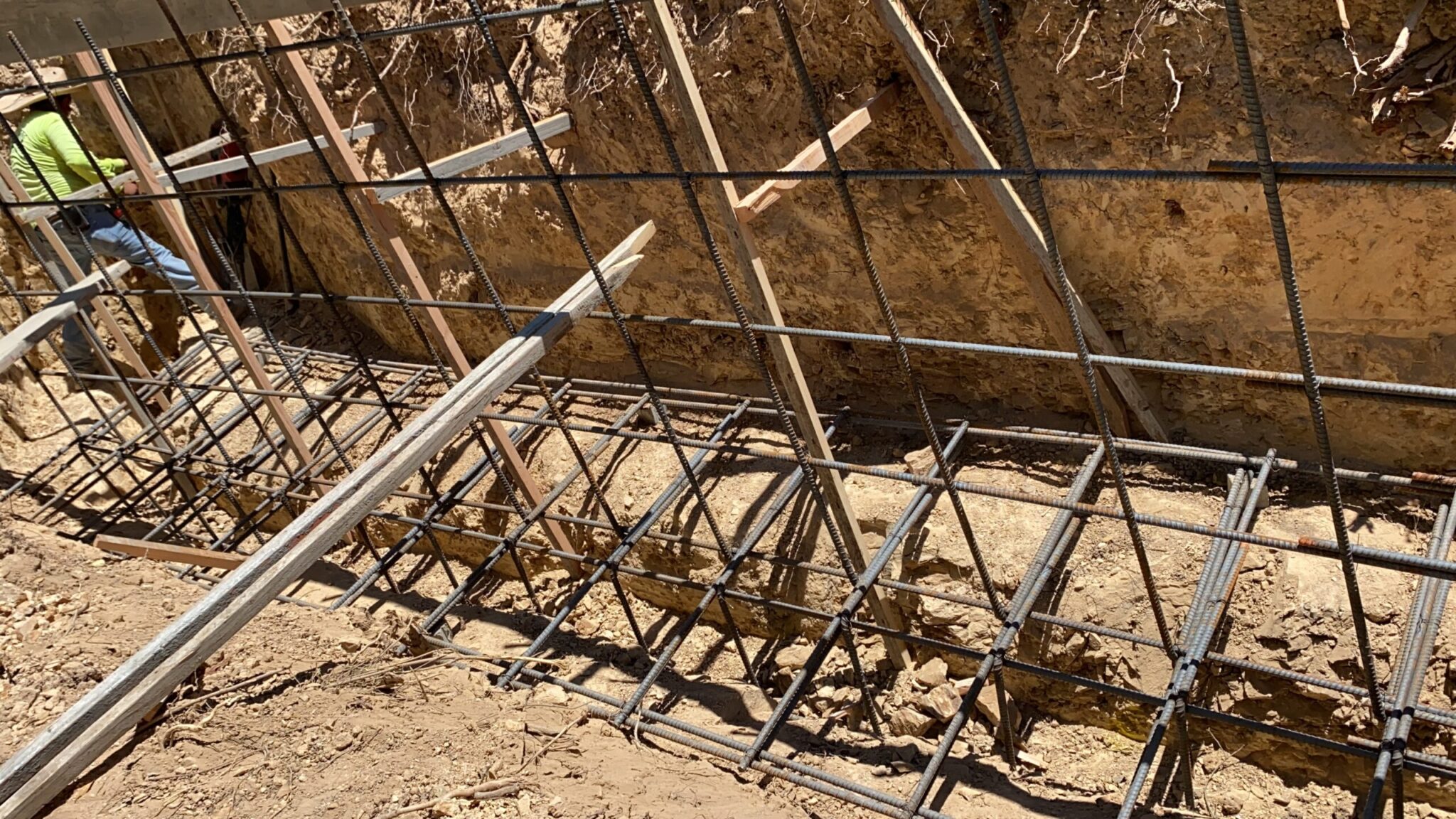
Long-term stability begins by establishing proper subgrade and base preparation. Unsuitable native soils, organic material, and saturated clays must be excavated and replaced with clean crushed stone, such as Caltrans Class 2 Aggregate Base. The subgrade and granular base must be placed in controlled lifts not exceeding 6 to 8 inches in loose depth. Each lift must be moisture-conditioned and mechanically vibrated to achieve 95% relative compaction under ASTM D1557 standards.
In areas prone to water infiltration or expansive soil movement, installing non-woven geotextile stabilization fabric between the native subgrade and aggregate base provides an effective separation barrier. This geotextile layer prevents fine soil particles from migrating upward into the stone base, maintaining structural drainage and preventing base aggregate from settling into the soil below.
Managing surface and subsurface runoff protects newly stabilized subbases from future erosion. Gutter downspouts must discharge away from flatwork edges, landscaping irrigation heads must point away from pavement perimeters, and joint sealants must be maintained to keep surface runoff above the pavement.
For commercial facility directors, retail managers, and HOAs facing sunken concrete walkways or uneven loading aprons, professional field evaluation ensures that repairs address root causes. The field operations team at We Love Paving (CSLB Licensed #1049649, C12 Earthwork and Paving) evaluates pavement elevations, identifies hidden subgrade voids, and delivers long-term repairs that keep your paved surfaces safe, attractive, and fully compliant with accessibility standards.